Launch Control
Camera Controller
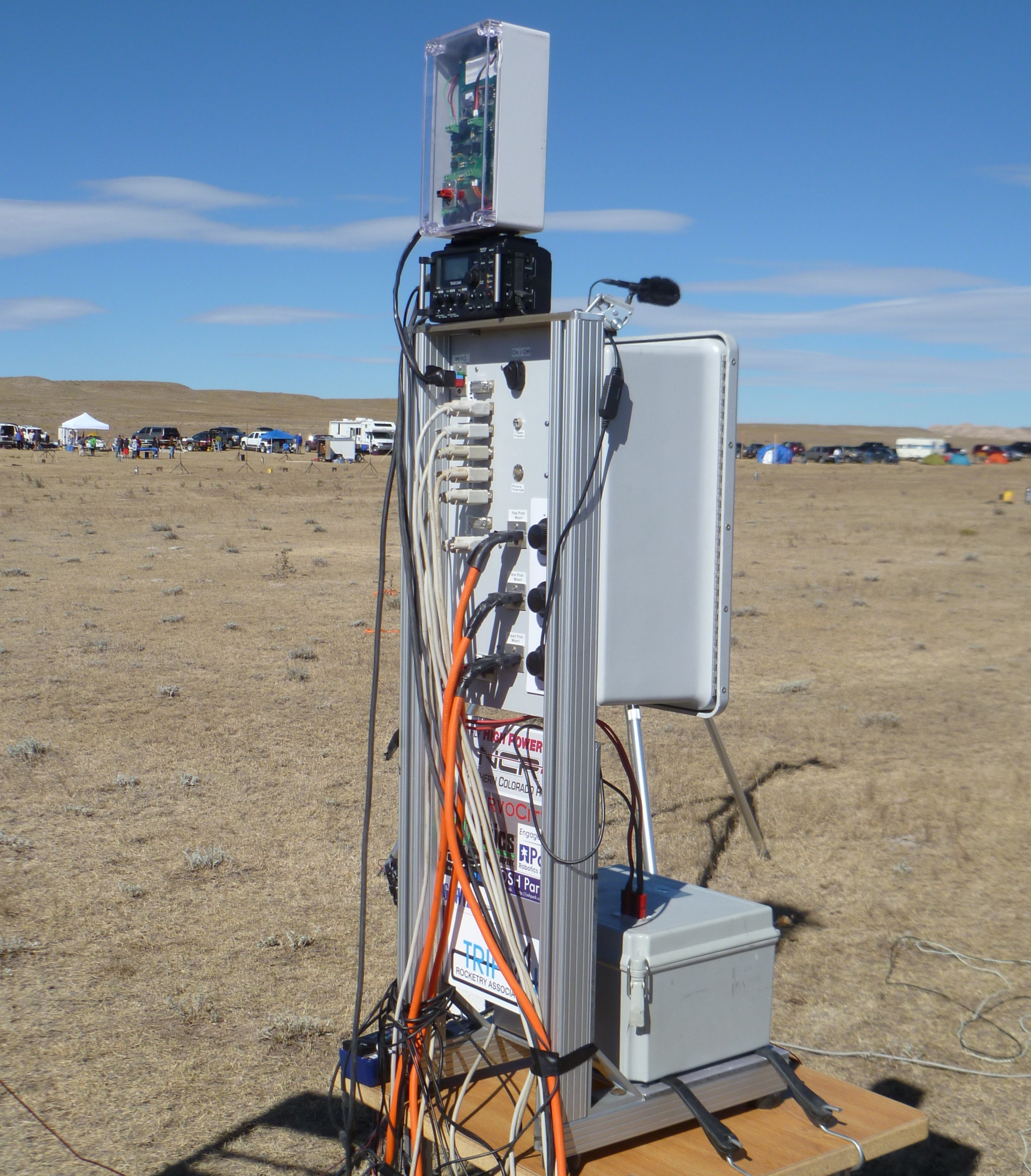
There have been several different versions of the launch set up and at the heart of it is the Camera Controller. The Camera Controller is a number of timers that are used to control the cameras as well as launches the rocket. It uses commercially off the shelf timers to perform the various sequence of events. For the earlier versions of the set up it was essential for the film cameras since a lot of money could be wasted running through film while the rocket was still sitting on the pad. Although not required for digital and video cameras, it is very covenant for editing purposes not having to go through minutes or hours of footage to find the few seconds at lift off. During the lift off the cameras may run only 20 seconds. This allows for smaller media cards to be used.
Details
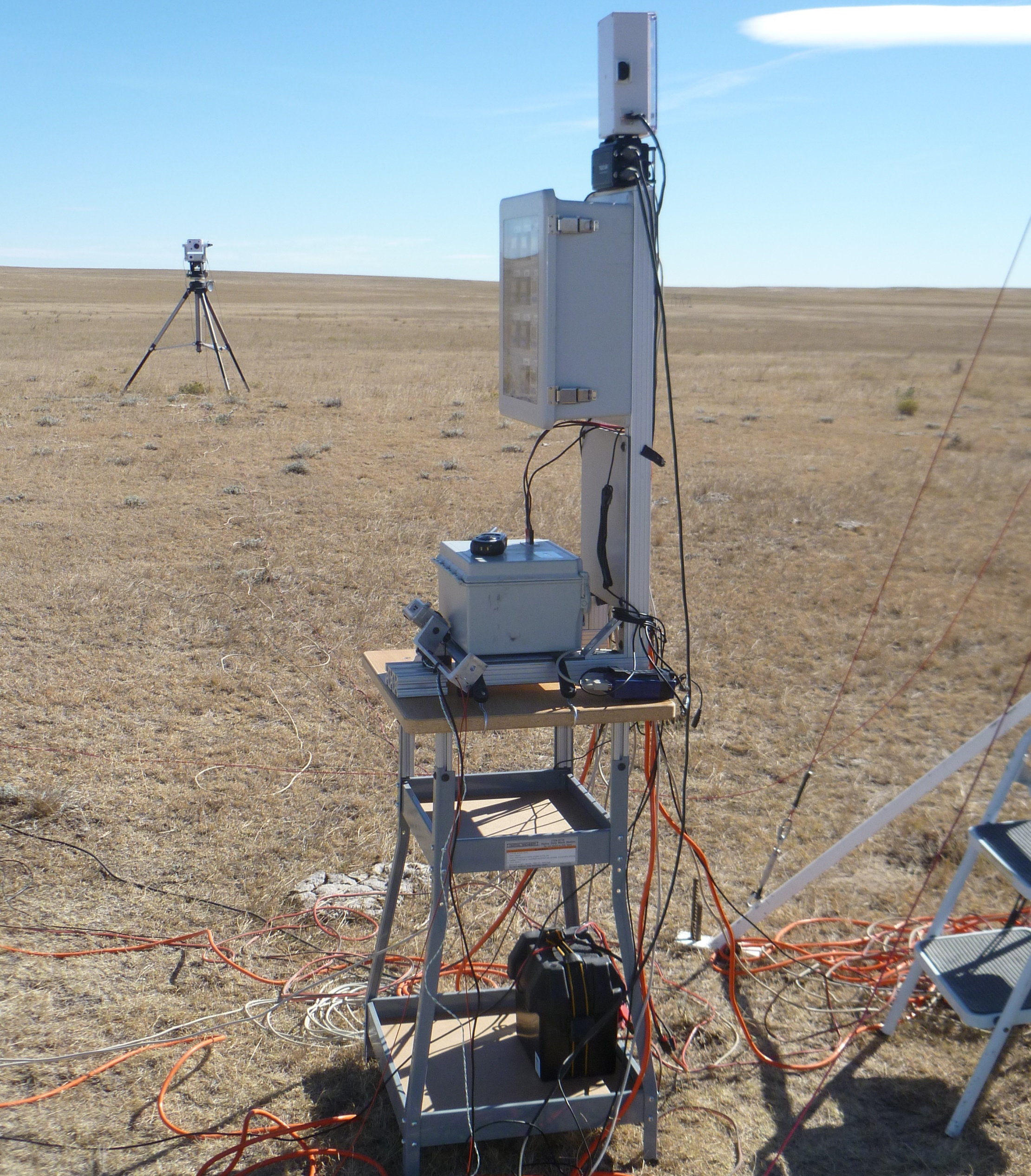
The timers are triggered by one of two events. Most of the cameras timers are triggered by the input from the LCO either by a wireless remote or directly from a clubs launch system. The remaining timers are triggered at lift off of the rocket by means of a launch detect switch on the rail. The outputs of the timers are connected to various electronics used to turn on and off the various functions of the cameras. The controller is connected to the cameras via off the shelf DB9 serial cables. The controller does not talk using serial communications but the serial cables are used because they are readily available and affordable. The Camera Controller interfaces with the camera with an interface board. This interface board provides the necessary outputs used to trigger the appropriate cameras.
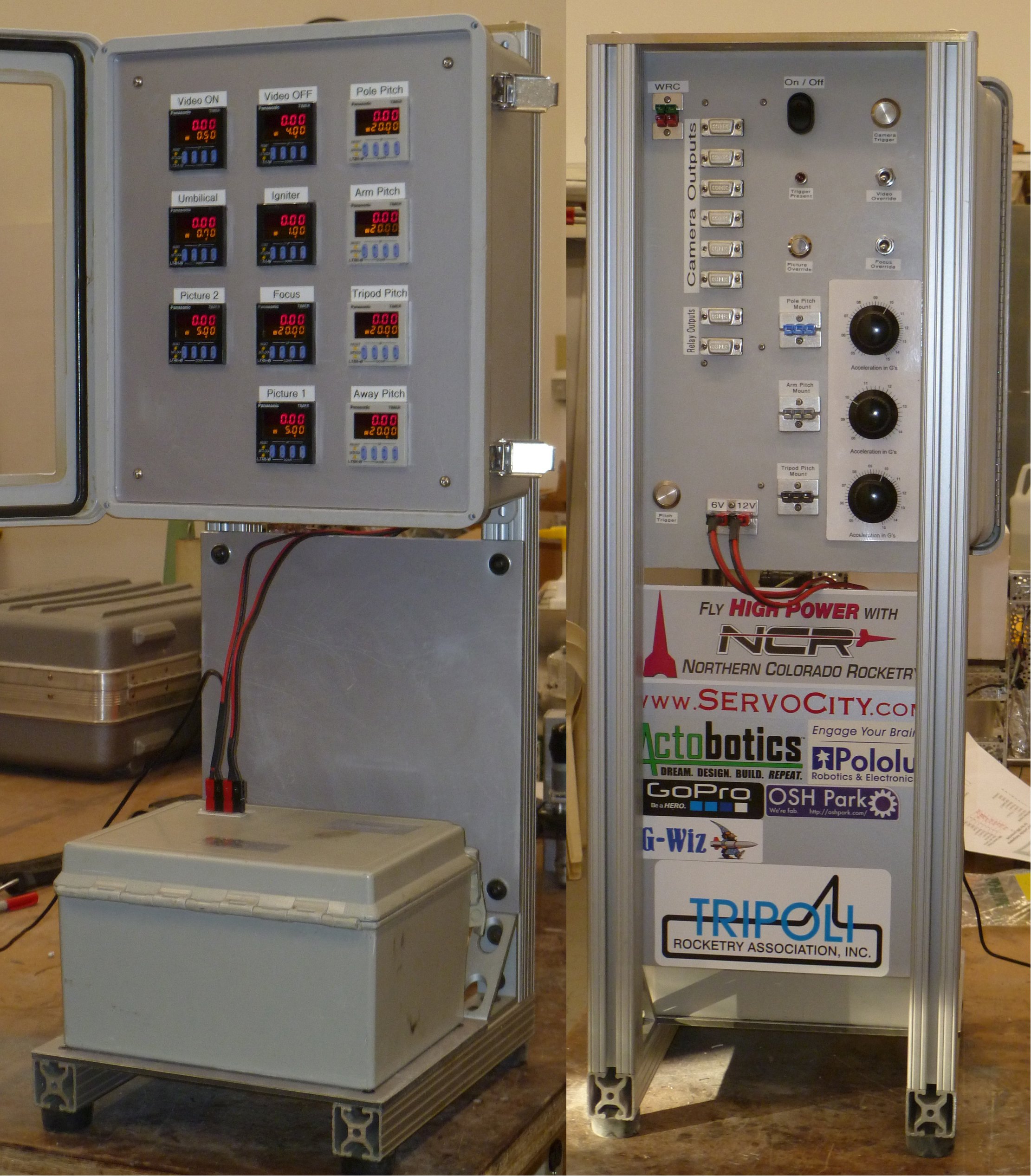
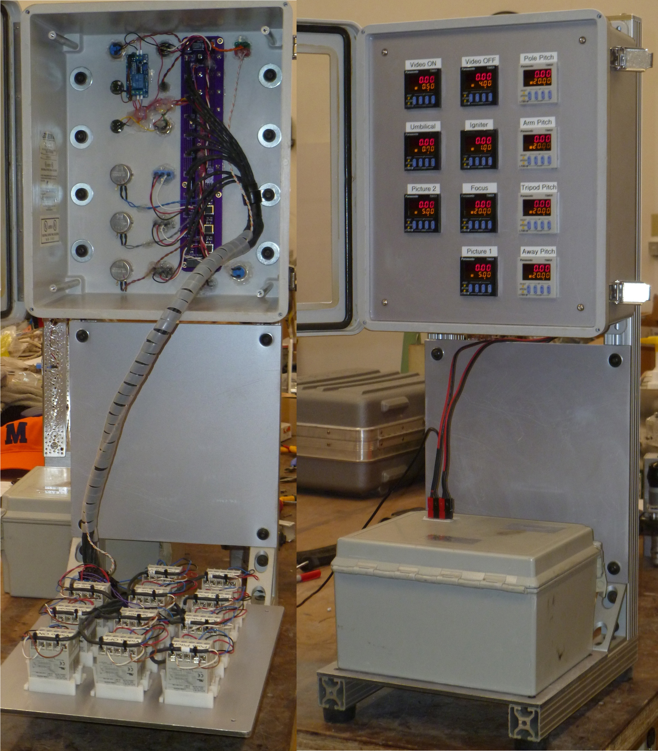
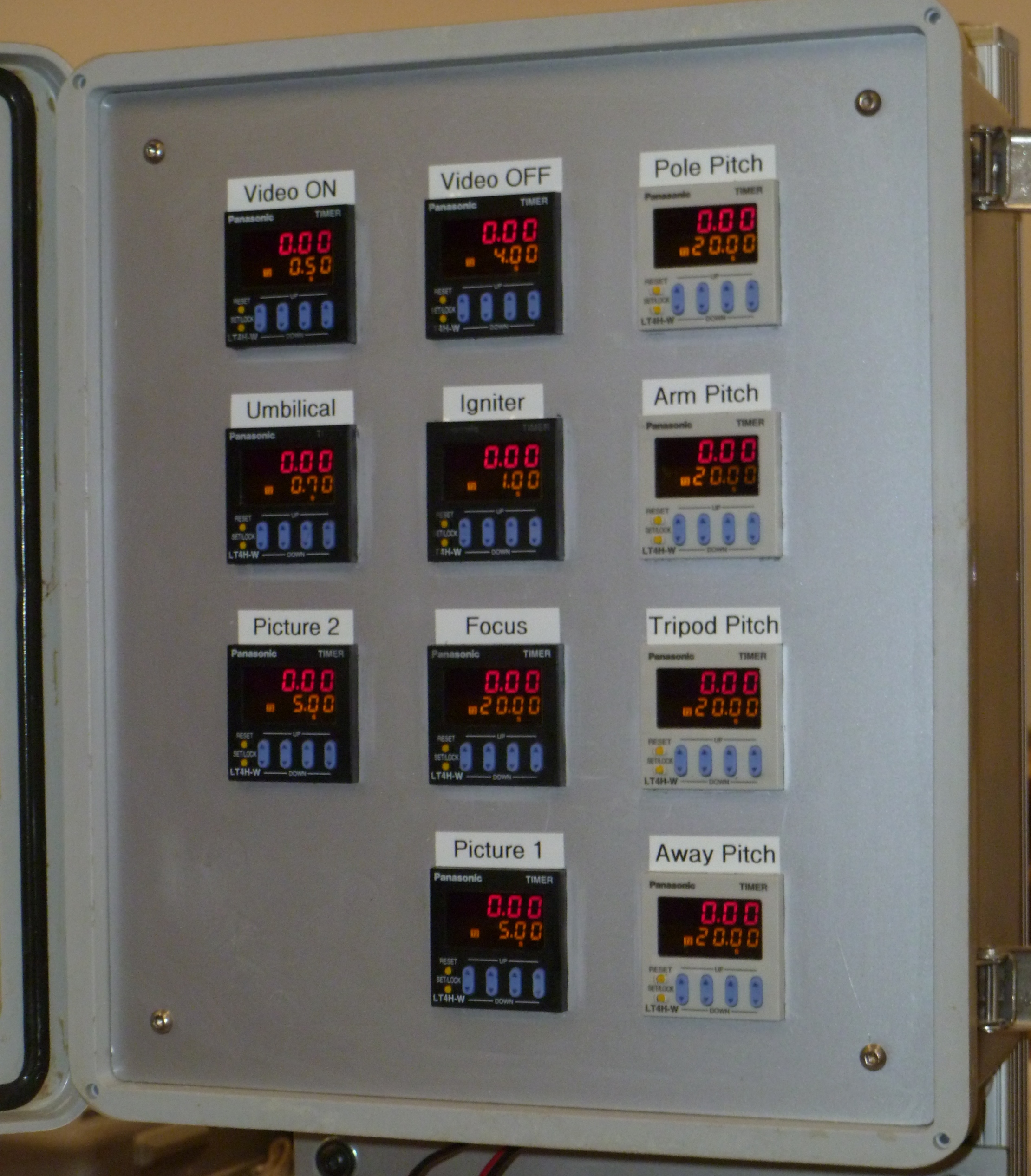
The timers can be programmed for a delay after trigger (T1) and the duration of the output (T2). The timers name and their functions are:
The VIDEO ON and VIDEO OFF timers controls the video cameras. Although the outputs are over the same line, two timers are needed, one for each event. Timers PICTURES 1 and PICTURES 2 are used for still cameras to trigger their shutter. Two timers may be used for the still cameras to stagger when each camera takes its pictures. They are used with timer FOCUS which may be required for some cameras to partially close the shutter button prior to taking pictures. The IGNITER timer is used to ignite the motor of the rocket. Although many of today's cameras can be wireless activated, their range is limited. The UMBILICAL timer is a dedicated used to trigger a camera on board the rocket just prior to lift off. Finally there are four PITCHING timers that are used to control the movement of some of the camera mounts.
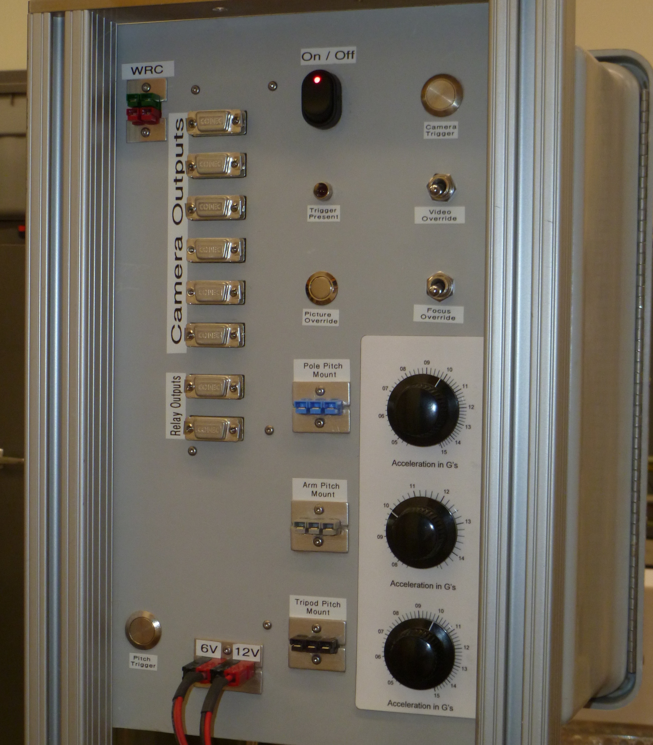
There are two types of outputs, the camera outputs and the relay outputs. This was done not only because of the two distinct types of outputs but also their location. At the base of the launcher outputs were needed for the igniter, and the umbilical as well as the input necessary to detect lift off while the cameras could be mounted in a variety of locations. All outputs are 12 volts and all have a common ground. The DB9 assignments are:
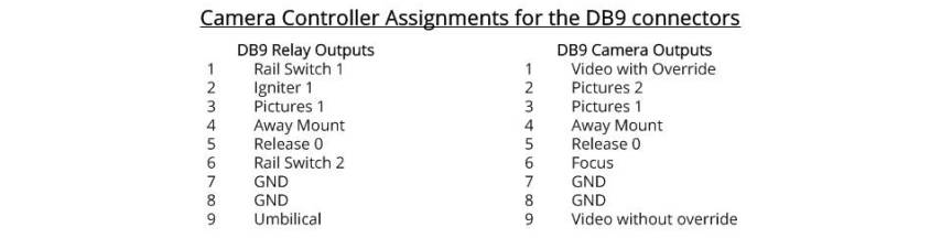
The reason there are two different video camera outputs is to have the ability to manually control some of the video cameras any time the need arises such as loading the rocket onto the launcher, installing the igniter, etc. This would be used to control video cameras that operate at normal speed such as the GoPro cameras. The Sony high speed video cameras would not use this output since they may not record sound and who need to see someone turning the arming switch in slow motion. Some outputs are common to both types of DB9 connectors. That is in part to the upgrading through the various versions of the controller. The RELEASE output is a special output that does not use a timer. Its output only occurs when the launch detect switch is activated. It is used to fire a charge that releases the slide mount.
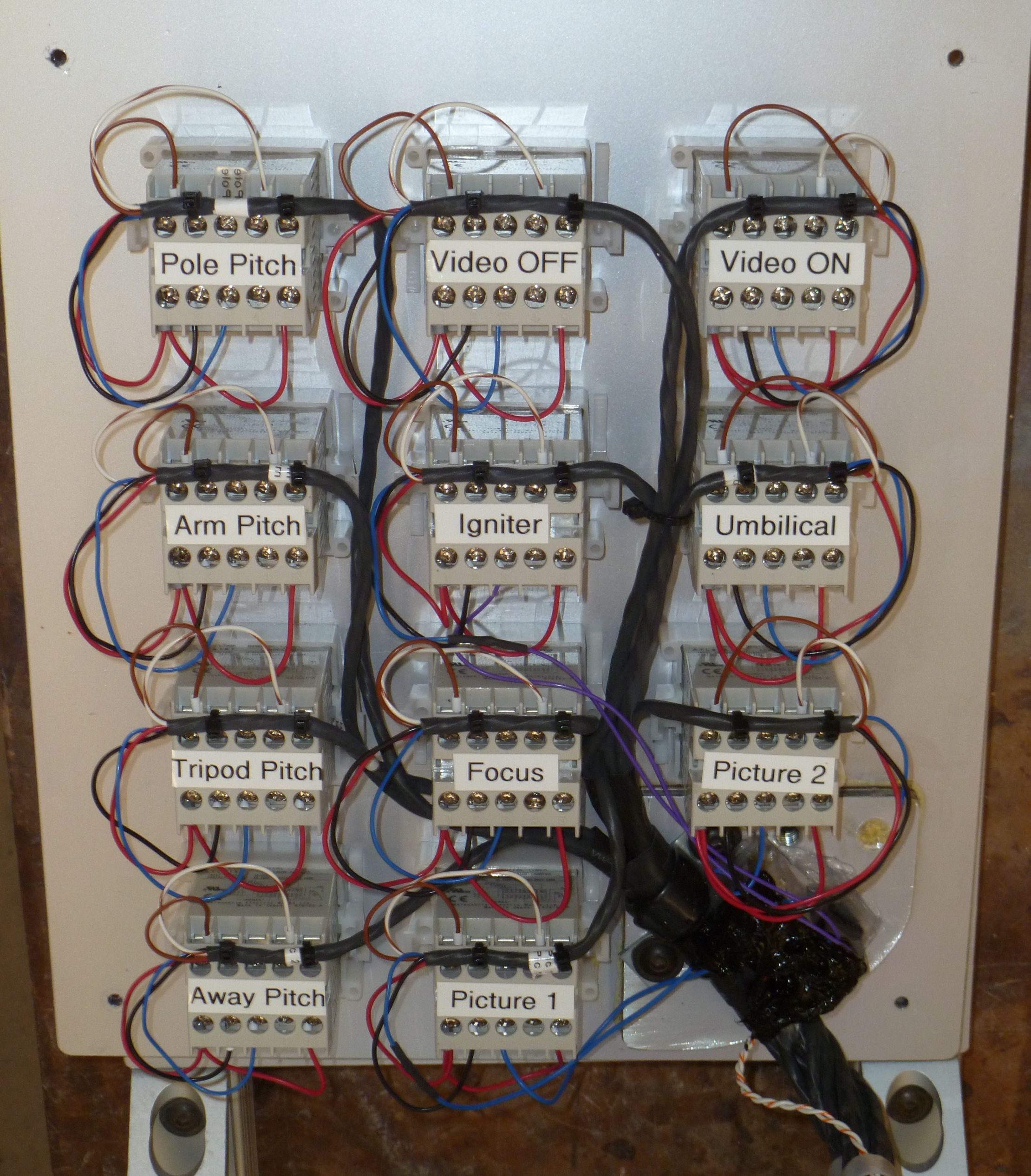
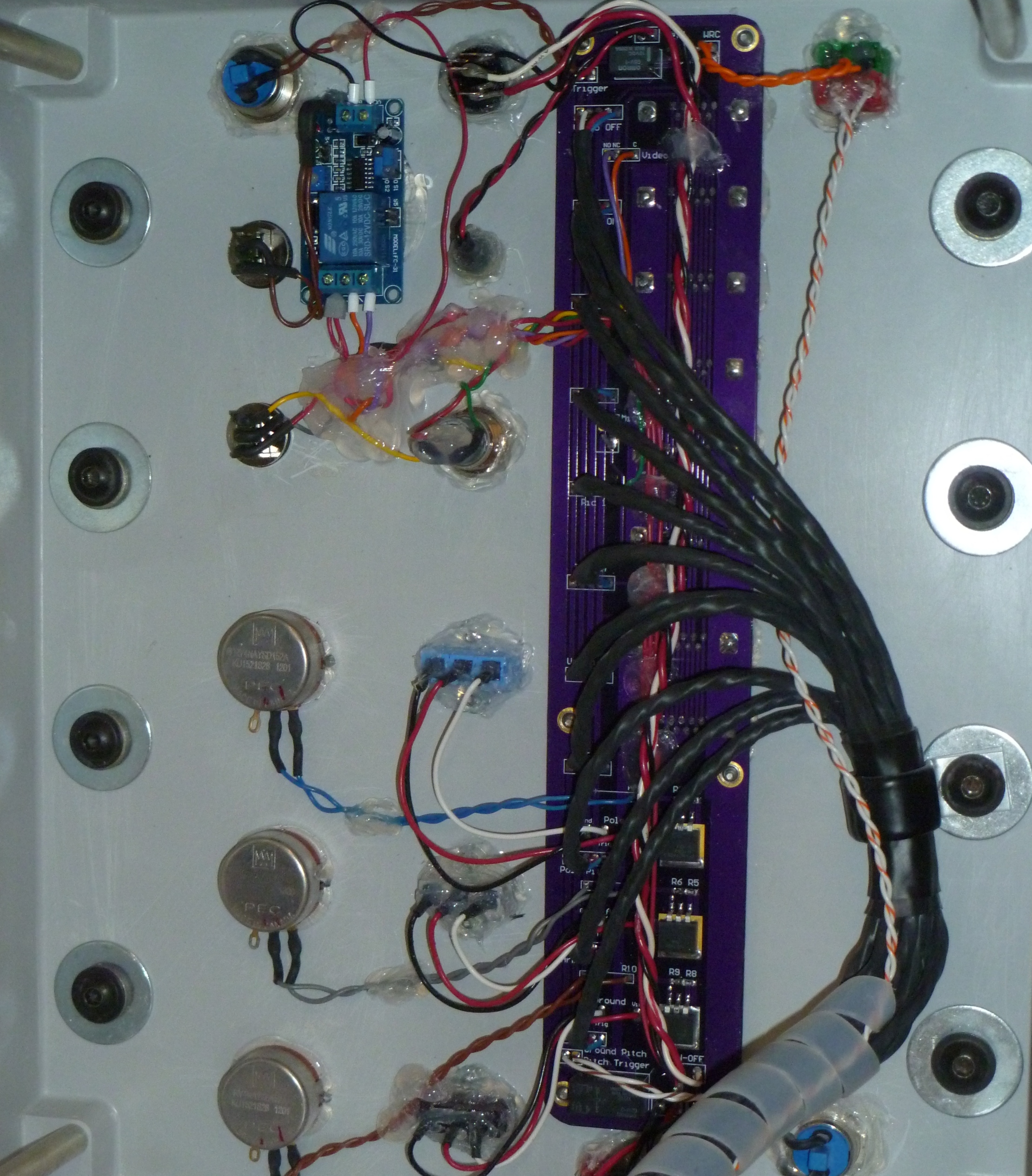
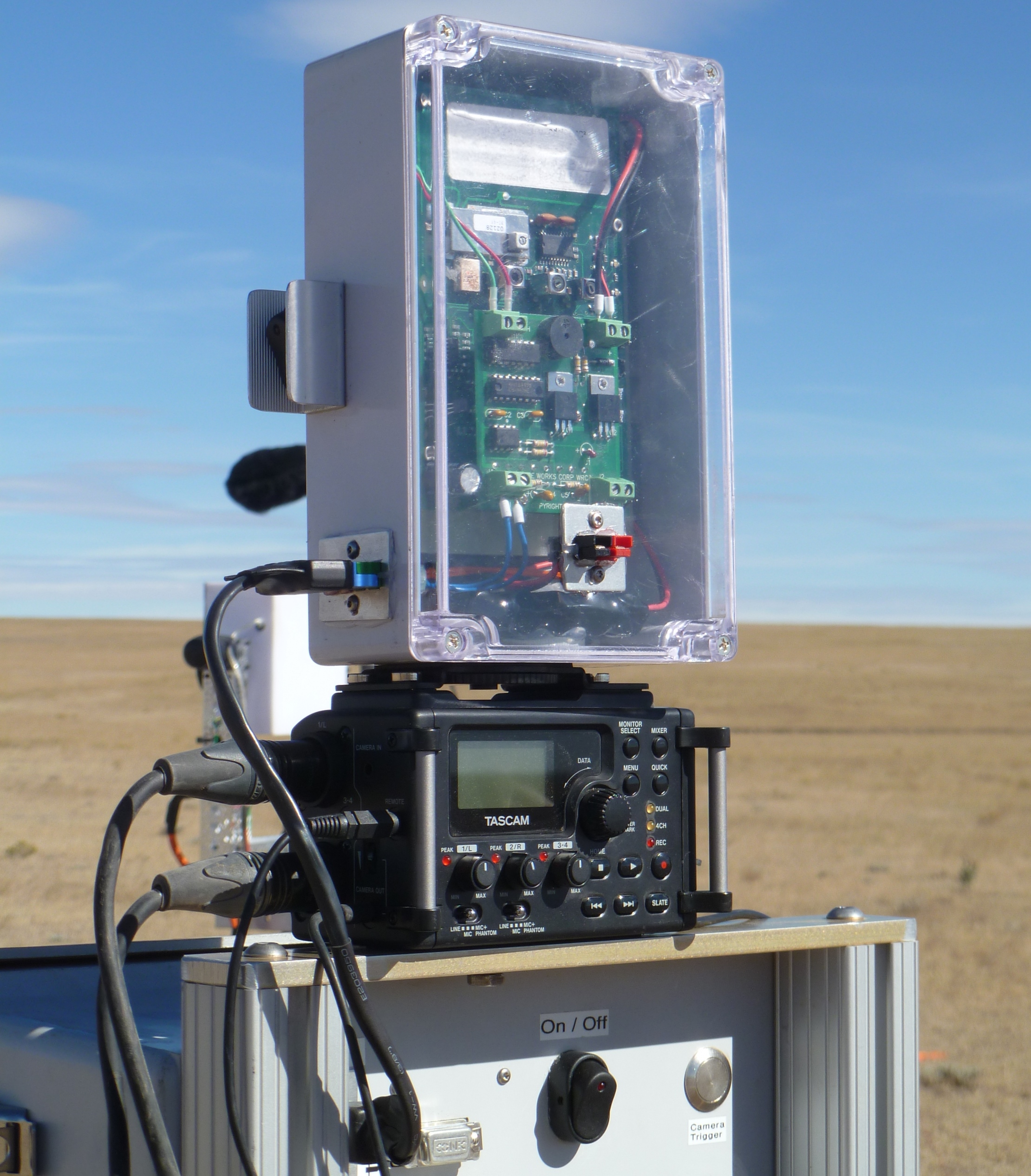
The Camera Controller circuit board has very few components. There are two relays used to trigger their respective timers. The relay from the WRC Trigger goes through a full wave rectifier so the polarity doesn't matter and it has a LED indicator to show when the external trigger is present. This safety feature is necessary so you don't turn on the controller when the trigger signal is present starting up the timers. Mostly the circuit board is just used to wire up the timers with the respective outputs. However, in addition the circuit board also provides an adjustable power supply to most of the pitching cameras to adjust the pitch rates for different rockets acceleration. There are also some manual switches to turn on the focus and take some still photographs as well as turn on the video cameras with override capability. There are also the manual trigger switches (one for the camera timers and another one for the pitching timers) that are used for bench testing. The Camera Controller is powered from two batteries, one 12V and the other 6V. The 6V battery is only used to provide enough headroom for the power supplies that are used for the pitching outputs.