Pitching Mount Design
The Theory
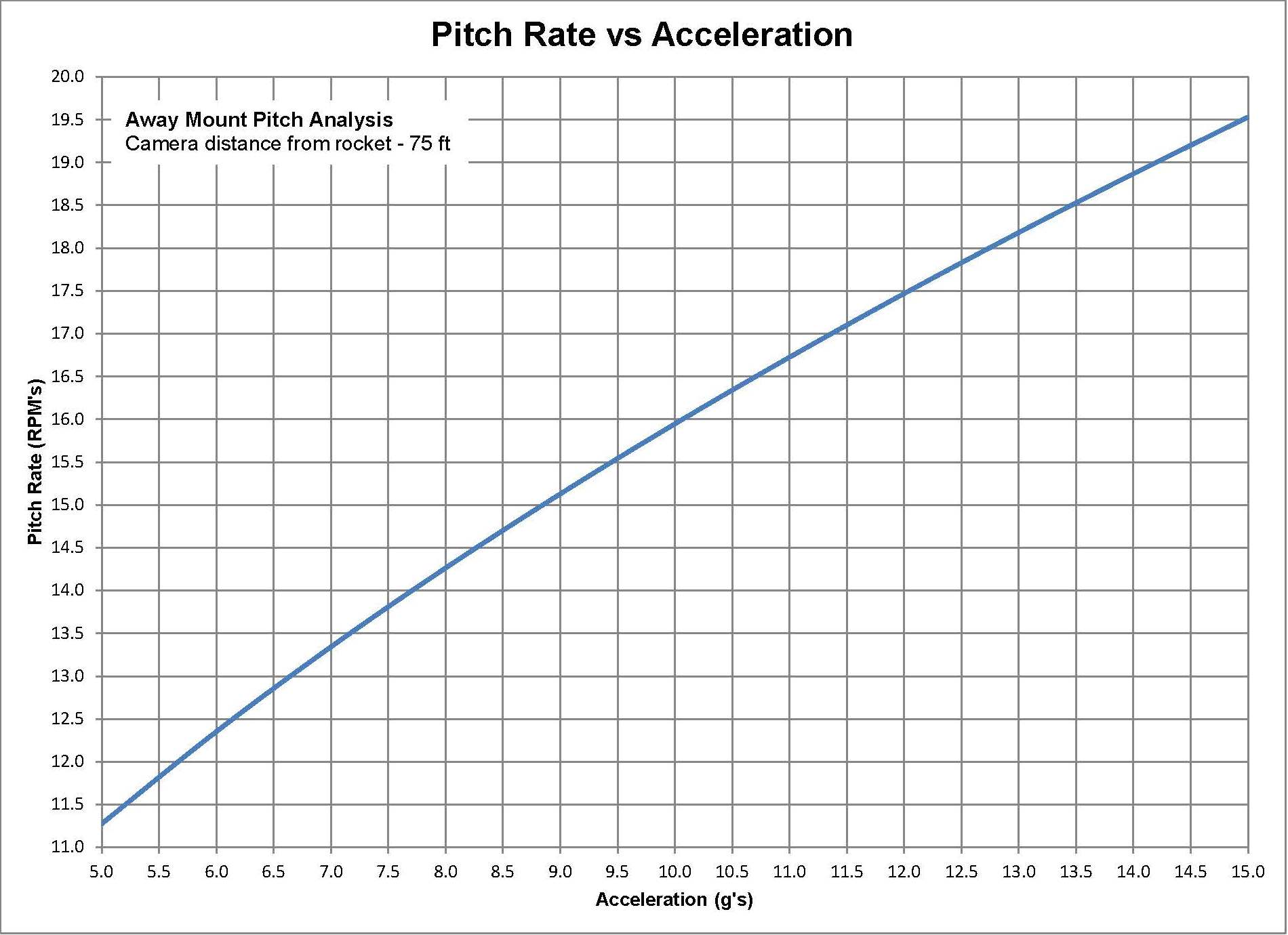
The description provided here is based on the Away Mount at a distance of 75 feet from the launch pad. However it can be shown that the distance is irrelevant. Of course some of the numbers change, the behavior of the camera mounts act the same and the numbers are proportional.
The idea behind the Pitching Design is based on a theoretical rocket accelerating at a constant value going straight up. Of course ones rocket does not have constant acceleration nor necessarily travel straight up but these assumption are acceptable. All these calculation can be performed on an ordinary spreadsheet.
Details
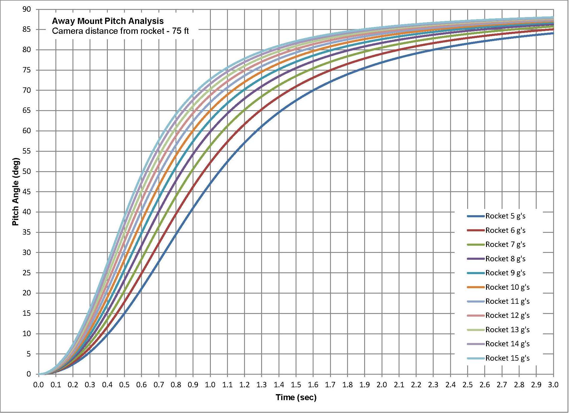
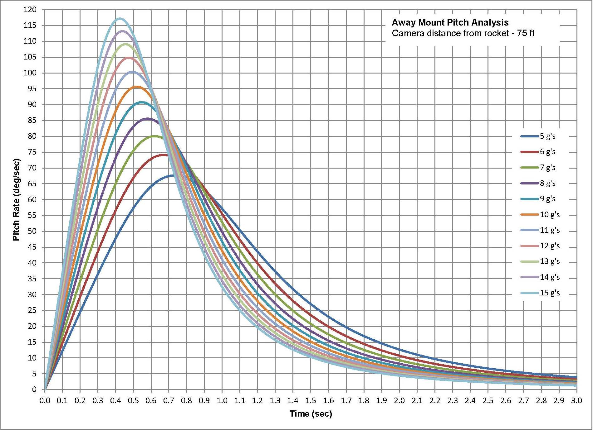
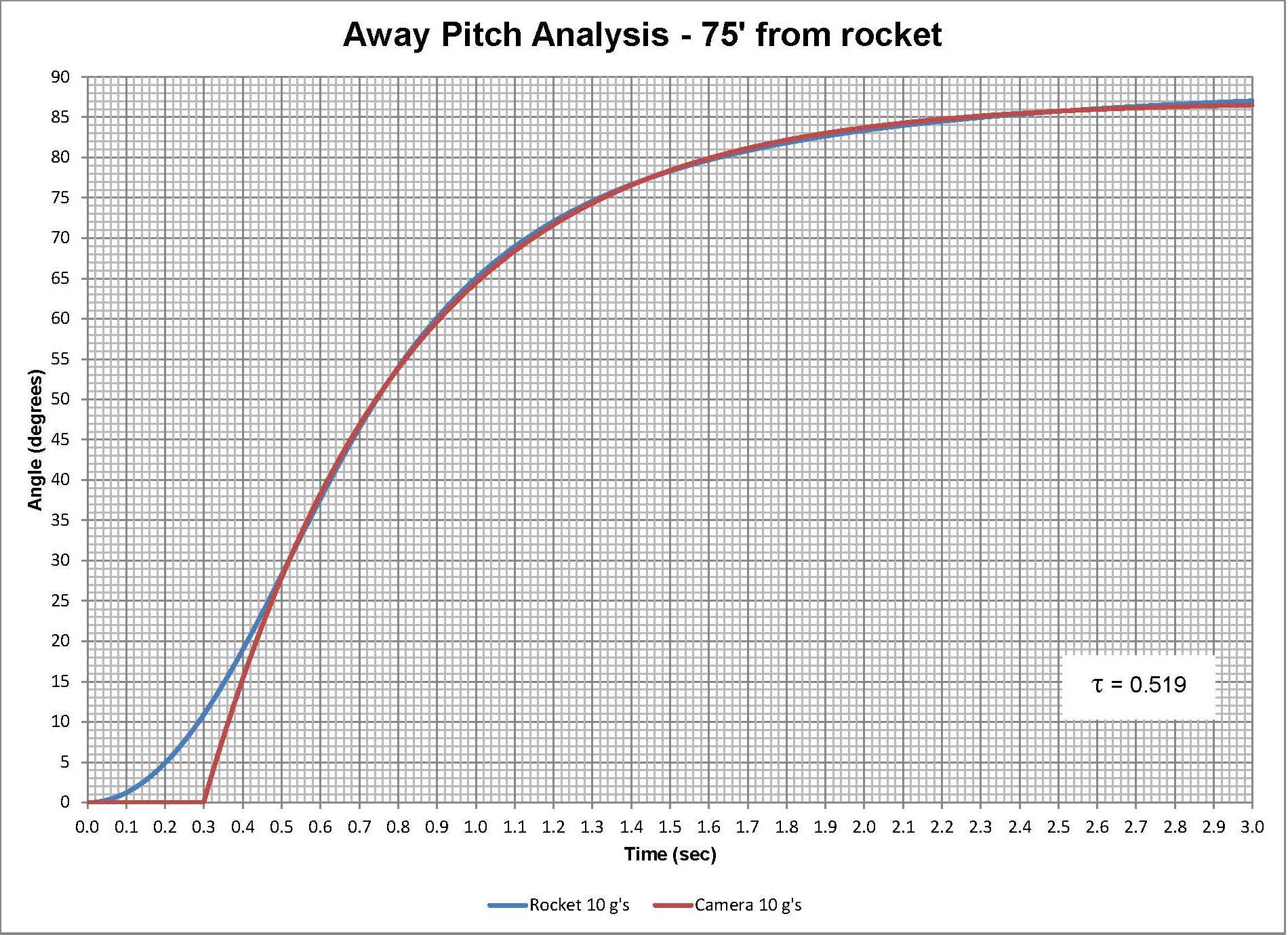
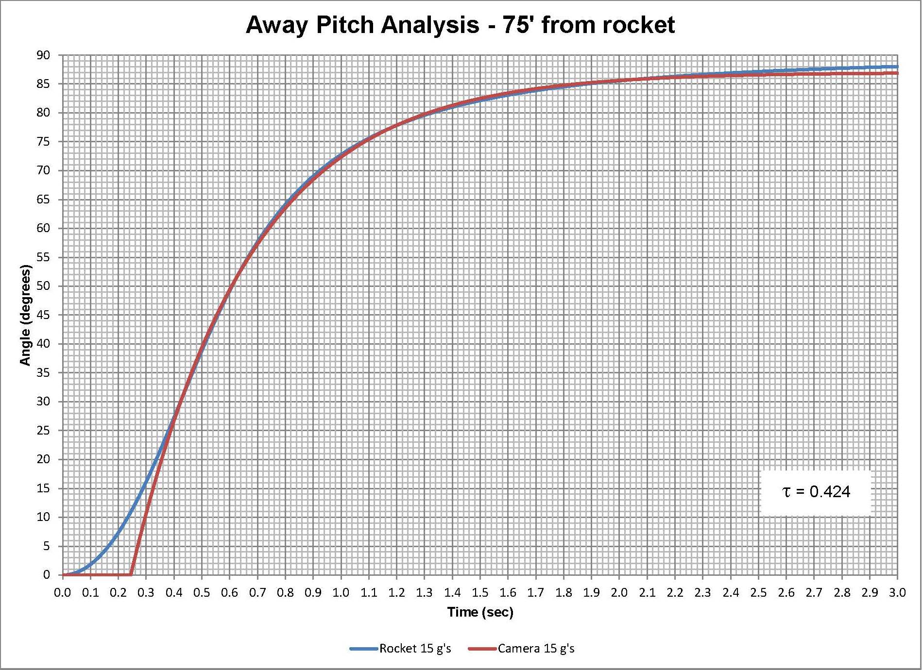
The angle the camera must be at the point at the rocket taking off is just the inverse tangent of the altitude of the rocket and the distance the camera is from the rocket. The altitude can be calculated based on the assumption of the constant acceleration. The angle is plotted as a function of time for various accelerations. The first plot shows this for rockets ranging from 5 to 15 G's which probably covers a vast majority of the High Power Rocket launching. The 'S' shaped curve is what one would expect. Calculating the slop of each curve provides the pitching rate the camera requires to track the rocket. Also as expected, the camera needs to start slow peak at some time and then slow as the rocket continue to gains altitude.
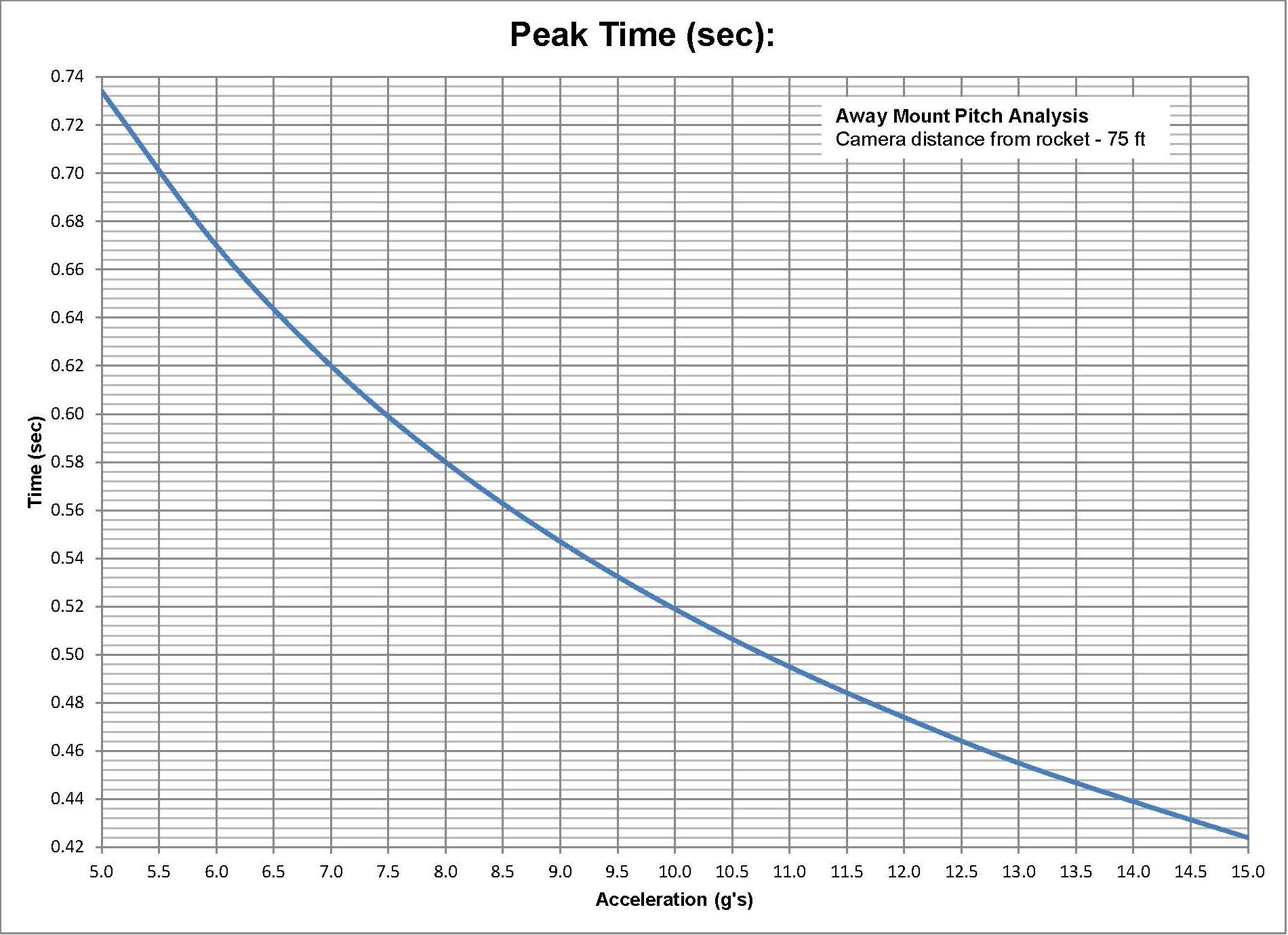
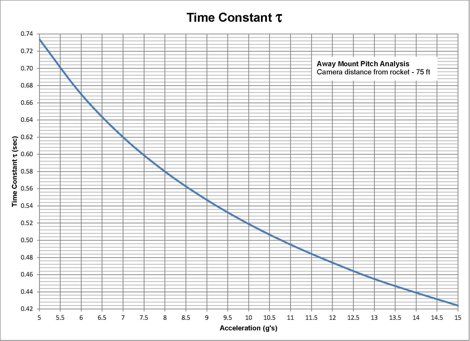
Also as one would expect, the peak pitch rate for a rocket accelerating at 15 G's occurs earlier and is higher than a rocket accelerating at only 5 G's. The magnitude of the Peak Pitch Rate determines how fast the motor must pitch the cameras. In this case it is about 115 degrees/second or about 19.5 RPM. As a reference, the Tripod Mount that is only 12 feet away has a Peak Pitch rate of over 290 degrees/second or 49 RPM. The time when the peaks occur also has meaning. For this example the peak pitch rates occur from about 0.42 to 0.74 seconds for 15 and 5 G's respectfully.
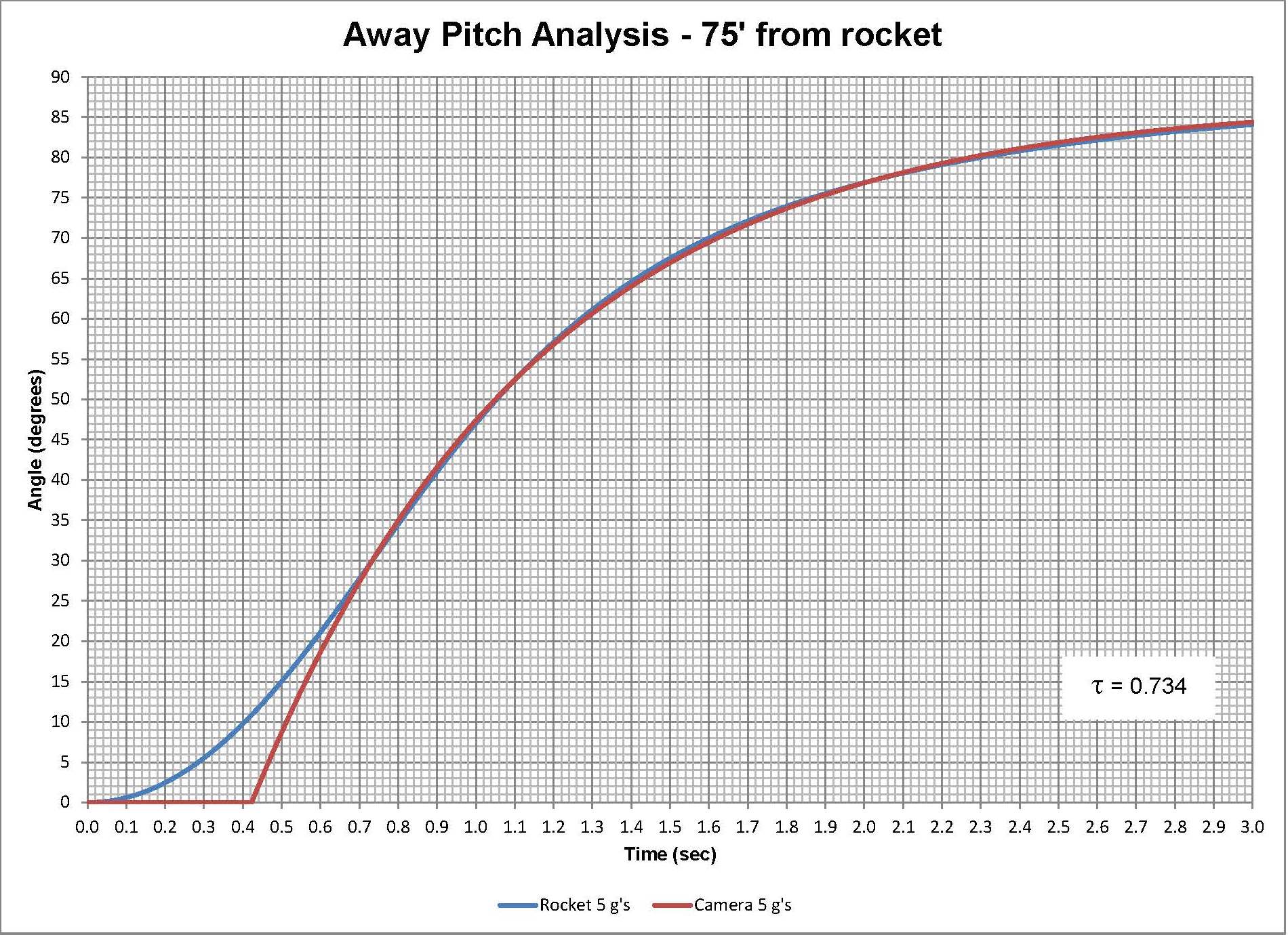
The pitching mechanism is simply a gear motor selected for the right RPM's needed and a PID motor controller with feedback. Details about PID controllers are abundantly available elsewhere so those details will not be discussed here except to say that the controller used is the Pololu Jrk 21v3 USB Motor Controller with Feedback. Methods used to set the parameters for the PID are described in the Pololu User's Guide. But with this controller set correctly, all one needs is an input signal to the motor controller that is the desired signal the camera mount needs to track the rocket (the first slide on this page). It turns out that using a simple resistor-capacitor (RC) circuit, the capacitor's voltage charges in a manner remarkable like the desired input.
Using the time for the peak pitch rate as the time constant tau and the correct amount of delay, the desired input signal is achieved. There are three graphs shown for the cameras desired angle for a rocket accelerating at 5, 10, and 15 G's, and the corresponding input signal that can be used by charging a capacitor using the simple RC circuit. Also remarkable is that the delay is directly proportional to the time constant tau. If one wants to change the distance from the rocket to the camera, the time constants will all change but the relationship is still the same i.e. the graphs still all look the same just the values are different.
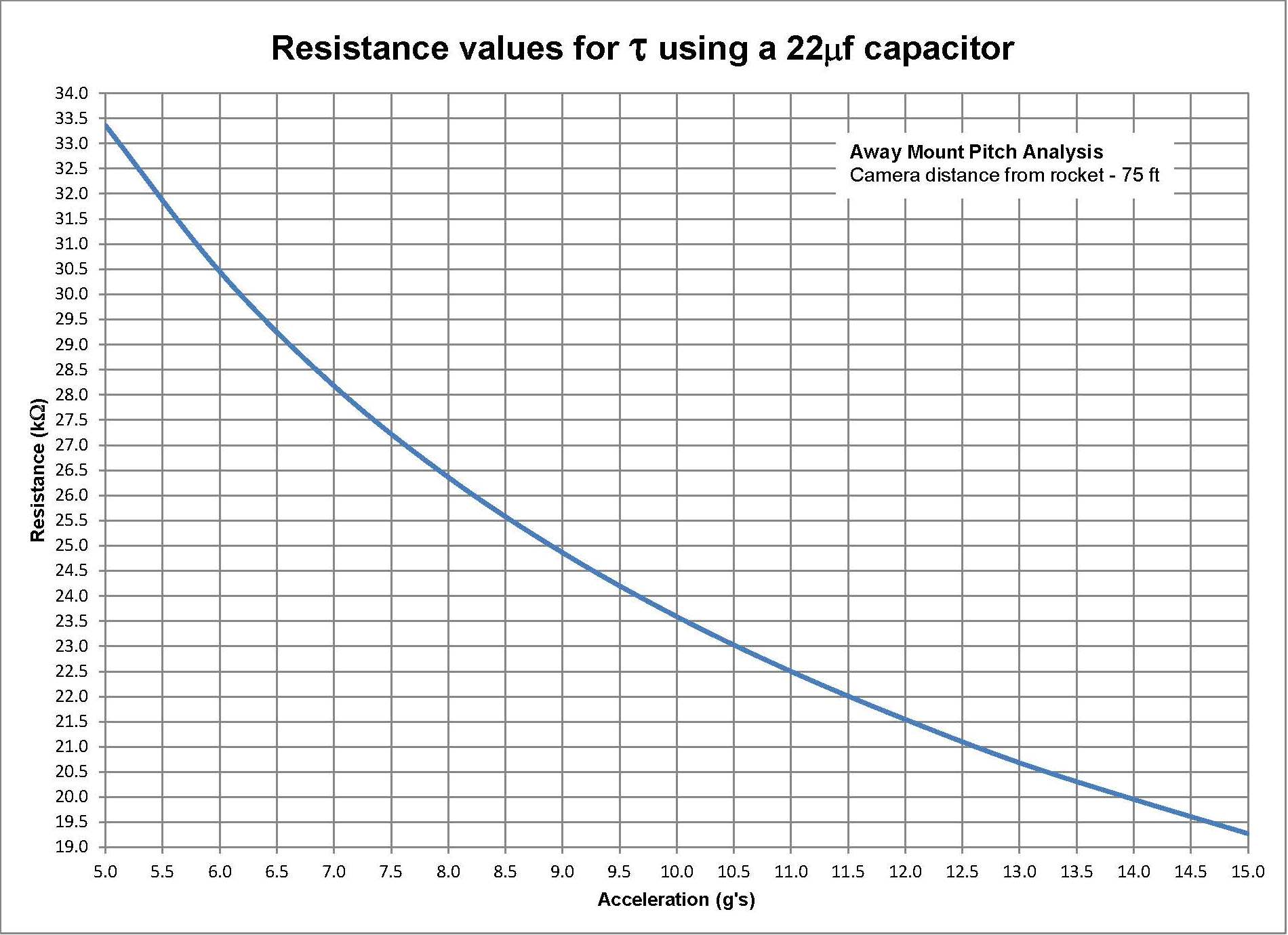
The time constant is easily adjustable since a potentiometer is just a variable resistor. For this example using a 22 microfarad capacitor the resistance values range from about 8.5 kOhms to 14 kOhms. So what about this delay, what can be done about that? The Pololu motor controller allows limits to be set for the start up acceleration of the motor. By limiting the motors start up acceleration a smoother heel can be achieved on the input signal. However there will still likely be a delay needed using the timers.